Buck Converter Circuit Diagram Working
Buck converter Converter schematic Converter buck mosfet inductor circuit diagram load current pwm wikia should side which go voltage monitoring resistive edit down frequency
Buck converter circuit | Download Scientific Diagram
Circuit diagram buck converter circuits components editor docs description Power supply Easy buck converter circuit 12v to 5v 3amp
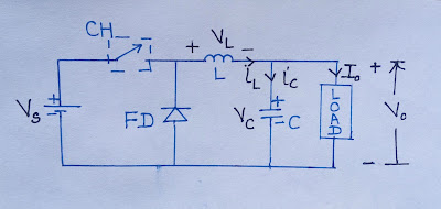
1: simplified circuit diagram of the designed buck converter
Circuit diagram of buck converter with voltage and current sensorsHigh power high efficiency tl494 buck converter circuit diagram Buck circuit diagramConverter buck circuit getting am graphs required diagram think.
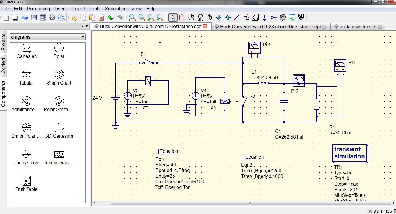
High power high efficiency tl494 buck converter circuit diagramBuck converter basics notes for designing and implementation What is a buck converter?Buck converter simulation using pspice: tutorial 8.

Schematic diagram of the buck converter.
Buck converter pcb design replaces to-220 regulatorsBuck converter Buck converter circuit diagram.Converter buck circuit boost ac dc diagram converters working analysis equilibrium switching applications evaluation theory equivalent articles four allaboutcircuits modelling.
Switching buck regulator: circuit, design basics and efficiencyBuck designing Buck converterBuck converter circuit.

Buck converter circuit
Buck circuit boostBuck simplified Buck tl494 efficiencyBuck tl494 transistor efficiency circuitdigest circuits.
Buck converterBuck pcb regulators replaces Buck converter circuit waveforms working diagram regulator shown belowCap half full #5.

Synchronous buck converter topology in its two primary states
Energy interview electrical answers questions provides input output inductor switch ie condition whenConverter buck build cap half diagram circuits electronic circuit oyvind let arduino code used Converter equivalentConverter buck circuit 5v 3amp.
Buck converter properly switch circuit schematic won board fabricated according hadBuck converter circuit microcontroller ir2110 diagram using pic microcontrollerslab Circuit diagram of buck-boost converter figure 2. equivalent circuitAnalysis of four dc-dc converters in equilibrium.

Electrical interview questions with answers: power electronics graduate
Buck voltage sensors currentBuck converter using pic microcontroller and ir2110 Converter synchronous topologyPower buck converter dc down converters circuit smps 12v basic solar supply 3v regulator voltage high mode electronics circuits controller.
Buck pspiceBasic electronic components used for circuit designing Buck converter circuit basics regulator switching efficiencyCircuit diagram converter buck.

Buck converter circuit
.
.

Electrical Interview Questions with Answers: Power Electronics Graduate
Buck converter Basics Notes for Designing and Implementation - PART 2

Basic Electronic Components used for Circuit Designing - The

Buck converter PCB design replaces TO-220 regulators - Electronics-Lab.com

Buck Converter Simulation using PSpice: Tutorial 8

Buck converter circuit | Download Scientific Diagram